Tuesday 31 March 2020

Configuration of Router as DHCP Server

DHCP is used to assign IP Addresses automatically over LAN .

This Blog will help us to understand how to configure Router as DHCP Server

This is will include very simple configuration steps

CONFIGURATION OF ROUTER AS DHCP SERVER


1) Configuration of LAN Interface on Router

=========================================
Router#
Router#config
Configuring from terminal, memory, or network [terminal]?
Enter configuration commands, one per line. End with CNTL/Z.
Router(config)#
Router(config)#int Gi0/0/0
Router(config-if)#ip address 10.0.0.1 255.255.255.0
Router(config-if)#description LAN
Router(config-if)#no shut
Router(config-if)#^Z

Router#

2) DHCP Server Configuration  on Router

============================================
Router(config)#ip dhcp pool dhcpvlan10
Router(dhcp-config)#network 10.0.0.0 255.255.255.0
Router(dhcp-config)#default-router 10.0.0.1
Router(dhcp-config)#^Z

Router#

3) Excluding few IP addresses from DHCP pool i.e making those IP address as static

==============================================================

Router(config)#ip dhcp excluded-address 10.0.0.2 10.0.0.5

4) Setting PCs for DHCP and verifying the IPs 

=======================================
PC CONFIGURED FOR DHCP 


5) Verification on Router 

========================

Router#sh ip dhcp pool

Pool dhcpvlan10 :
Utilization mark (high/low) : 100 / 0
Subnet size (first/next) : 0 / 0
Total addresses : 254
Leased addresses : 3
Excluded addresses : 1
Pending event : none

1 subnet is currently in the pool
Current index     IP address                    Leased/Excluded/Total

10.0.0.1             10.0.0.1 - 10.0.0.254          3 / 1 / 254

Router#sh ip dhcp binding 
IP address       Client-ID/              Lease expiration        Type
                 Hardware address
10.0.0.6         0000.0CB0.4A54           --                     Automatic
10.0.0.7         0090.218C.C7ED           --                     Automatic
10.0.0.8         0030.A397.E307           --                     Automatic


Hope you all find the blog useful !!!!


Thanks for Reading !!!!!

Monday 30 March 2020

IPV6 CHAPTER 5 Types of IPV6 Unicast Addresses

Unicast Address


Used when one host to one host communication is desired.
Example –Unicast address will be used when Host A wants to communicate with Host B.

Global Unicast Address
Unique-Local Address
Link-Local Address

Global Unicast Address

These are equivalent to IPv4’s public address.
These are globally addresses which are unique.
Routable  globally
Assigned by IANA
First 3 bits are always 001 .
Always start with 2 or 3

Unique Local Address(ULA)

These are globally unique IP addresses but used for local communication.
Routable but not in IPV6 Global prefix table.
First 7 bits are always 1111 110.
Always start from FC or FD.

Link Local Address

Auto configured IP address once IPv6 is enable or configured.
These addresses are not routable, so a Router never forwards
Used for communication among IPv6 hosts on a link (within domain)

First 16 bits are set as 1111 1110 1000 0000  & the next 48-bits are set to 0
Always starts with FE80:0000:0000:0000

Thanks for Reading !!!!

Sunday 29 March 2020

IPV6 CHAPTER 4 IPV6 ADDRESSING MODES

IPV6 Addressing Modes


Unicast 

Multicast

Anycast

Note :- In IPV4 we have  Unicast , Multicast and Broadcast . There is no Broadcast address in IPV6.


Unicast Addressing Mode


Used when one host to one host communication is desired.
Example –Unicast address will be used when Host A wants to communicate with Host B.
                                                                                             
Global Unicast Address
Link-Local Address
Unique-Local Address

Multicast Addressing Mode 


Used when one host to many (a group of hosts) hosts communication is desired.
The multicast information is send on an special multicast address and all the hosts which are in that multicast group receives the information.
Range – FF00::/8
All node on link
Address – FF02::1

Anycast Addressing Mode 


New type of addressing introduced.
It is different from Broadcast.
In this addressing mode, multiple interfaces are assigned with same Anycast IP address.
When a host wishes to communicate with a host equipped with an Anycast IP address, it sends the  message. With the help of complex routing mechanism, that message is delivered to the host closest to the Sender in terms of Routing cost.

Saturday 28 March 2020

IPV6 CHAPTER 3 - Making IPV6 Address Short


We saw that IPV6 is 128bits and represented in Hexadecimal number system.
Binary Number System Representation
•    0010000000000001 0000000000000000 0000000000000000 0000000000000000 0000011000010100 0000000000000000 0000000000000000 1011110110000000
Hexadecimal Number System Representation
2001:0000:0000:0000:0614:0000:0000:BD8


Making IPV6 address short

2001:0000:0000:0000:0614:0000:0000:BD80
Rule 1 :- Leading Zeros can be discarded.
2001:0:0:0:614:0:0:BD80
Rule 2:- We can once replace consecutive two or more blocks containing zeros by double colon : :
2001::614:0:0:BD80

Thanks for Reading!!!!
                                                                                             

Friday 27 March 2020

IPV6 CHAPTER 2 - IPV6 ADDRESS FORMAT

Will Focus on :-


  • Hexadecimal Number System
  • Understanding IPV6 Address Structure
  • Splitting IPV6 addresses  
  • IPV6 – CIDR Representation.


Hexadecimal Number System


IPV6 addresses are 128 bits addresses.
IPv6 addresses are written using hexadecimal.
Before learning IPv6 Address Format.
Let’s First Understand Hexadecimal Number System .

HEXADECIMAL NUMBER SYSTEM

IPV6 ADDRESS FORMAT

IPV6 is I28 bits address. 
Divided into 8 blocks . 
Each block having 16 bits .
Each block is represented in 4 digit Hexadecimal number.
Each block is separated by colon 


IPV6 ADDRESS FORMAT

Example :-
0010000000000001 0000000000000000 0000000000000000 0000000000000000 0000011000010100 0000000000000000 0000000000000000 1011110110000000

Splitting IPV6 Addresses

The 128 bits IPV6 address is split into two 64 bits segments the top 64 bits is the network part and the lower 64 bits the host part.
Host part is automatically calculated by the host itself.
eg. 
2001:0000:0000:0000:0614:0000:0000:BD80

CIDR Notation

2001:0000:0000:0000:0614:0000:0000:BD80 /64
64 => Network Prefix Length
Represents the number bits used for Network .

                                                                                              
Thanks for Reading !!!!

Thursday 26 March 2020

IPV6 CHAPTER 1 - Introduction to IPV6


IPv6 stands for Internet Protocol version 6
IPv6 was developed by the Internet Engineering Task Force (IETF).
New version of IP Protocol which is in use.
IPv6 was also called IPng in the early days of IPv6 protocol development stage.


WHY NOT IPV5 ?

•IPv5 is used for Experimental purposes .
•Known as “Internet Stream Protocol                                                                                             
•Introduction to IPV6
•IPV6 is mainly deployed since already existing IPV4 is running out of addresses .
•IPv4 is 32 bits .
•Provided 2^32 =4294467295 (about 4.3billion) IP addresses.
•For IPV4 Different Techniques were introduced –Subnetting , NAT. But still there will be storage of IP addresses.
                                                                                             

Features of IPV6

•IPV6 is 128 bits.
•Provides 2^128=
340,282,366,920,938,463,463,374,607,431,768,211,456
          340 trillion trillion trillion addresses
•Bigger Address Space as compared to IPV4.
•Using IPV6 we can assign IP address to every possible things.
•NAT not required.
•No Broadcast (Anycast is introduced)
                                                                                             

Features of IPV6

•Header Format is simple as compared to IPV4
•IPv6 contains 6 basic header field whereas IPV4 has 12.
•Faster Processing.
•Inbuilt IPSec (now optional)
Stateless auto configuration - No more need to configure IP addresses for end devices since Device gets IPV6 address by including its own MAC Address.
•Built-in support for QoS tagging.
•Built-in support for IP Mobile (IP address Mobility)                                                                                            
Thanks for Reading !!!!

Wednesday 25 March 2020

Add , Remove & Resequence entries in ACL

Today in this post we will see how to add , remove and resequence entries in an ACL.
               
So we have an existing acl named techstuff


Let's check this acl.


R1#sh ip access-lists techstuff

Extended IP access list techstuff

    10 permit ip 10.0.0.0 0.0.0.255 any

    20 permit ip 20.0.0.0 0.0.0.255 any

    30 permit ip 30.0.0.0 0.0.0.255 any

    40 permit ip 40.0.0.0 0.0.0.255 any

    50 permit ip 50.0.0.0 0.0.0.255 any


Now , Need to deny host 20.1.1.1 in the ACL

Hence need to add the entry before entry with sequence number 20


R1(config)#ip access-list extended techstuff

R1(config-ext-nacl)#15 deny ip host 20.1.1.1 any

R1(config-ext-nacl)#do sh ip access-list techstuff

Extended IP access list techstuff

    10 permit ip 10.0.0.0 0.0.0.255 any

    15 deny ip host 20.1.1.1 any <--------------- New entry

    20 permit ip 20.0.0.0 0.0.0.255 any

    30 permit ip 30.0.0.0 0.0.0.255 any

    40 permit ip 40.0.0.0 0.0.0.255 any

    50 permit ip 50.0.0.0 0.0.0.255 any


Now lets see how to remove an entry


R1(config)#ip access-list extended techstuff

R1(config-ext-nacl)#no 40

R1(config-ext-nacl)#do sh ip access-list techstuff

Extended IP access list techstuff

    10 permit ip 10.0.0.0 0.0.0.255 any

    15 deny ip host 20.1.1.1 any

    20 permit ip 20.0.0.0 0.0.0.255 any

    30 permit ip 30.0.0.0 0.0.0.255 any

    50 permit ip 50.0.0.0 0.0.0.255 any


Here we can see the start sequence number is 10 but the intervals between the entries are not even


Lets make the interval as 10


R1(config)#ip access-list ?

  extended    Extended Access List

  log-update  Control access list log updates

  logging     Control access list logging

  resequence  Resequence Access List

  standard    Standard Access List


R1(config)#ip access-list reseque

R1(config)#ip access-list resequence ?

  <1-99>       Standard IP access-list number

  <100-199>    Extended IP access-list number

  <1300-1999>  Standard IP access-list number (expanded range)

  <2000-2699>  Extended IP access list number (expanded range)

  WORD         Access-list name


R1(config)#ip access-list resequence techstuff ?

  <1-2147483647>  Starting Sequence Number


R1(config)#ip access-list resequence techstuff 10 ?

  <1-2147483647>  Step to increment the sequence number


R1(config)#ip access-list resequence techstuff 10 10

R1(config)#^Z


R1#sh ip access-list techstuff

Extended IP access list techstuff

    10 permit ip 10.0.0.0 0.0.0.255 any

    20 deny ip host 20.1.1.1 any

    30 permit ip 20.0.0.0 0.0.0.255 any

    40 permit ip 30.0.0.0 0.0.0.255 any

    50 permit ip 50.0.0.0 0.0.0.255 any


Hope Guys !!! You find this blog informative and useful !!!

Thanks!!!!

Tuesday 24 March 2020

Adding Remarks to Entries in Active ACL

In this blog will show you have to add remarks to entries in an active ACL .

"Remarks" are logically associated with entries in ACL .


They are nothing but the comments given to the entries in an ACL which helps Network administrator to get some information regarding the particular entry in the ACL. 


Now let's check an existing ACL named "techstuff" configured in Router R1

R1#sh ip access-lists techstuff

Extended IP access list techstuff
    10 permit ip 10.0.0.0 0.0.0.255 any
    20 deny ip host 20.1.1.1 any
    30 permit ip 20.0.0.0 0.0.0.255 any
    40 permit ip 30.0.0.0 0.0.0.255 any
    50 permit ip 40.0.0.0 0.0.0.255 any


Alway remember Guys!!! sh ip access-list wont show you any remarks .


To view remarks you need to check the show run of the router 

R1#sh run | begin techstuff

ip access-list extended techstuff
 permit ip 10.0.0.0 0.0.0.255 any
 deny   ip host 20.1.1.1 any
 permit ip 20.0.0.0 0.0.0.255 any
 permit ip 30.0.0.0 0.0.0.255 any
 permit ip 40.0.0.0 0.0.0.255 any
!

Here you can check there is no remark yet configured for this ACL . 

Lets do for the entry with sequence no.20 which is denying the host 20.1.1.1 for any destination . 


R1(config)#ip access-list ex techstuff

R1(config-ext-nacl)#no 20
R1(config-ext-nacl)#remark ** DONT ALLOW 20.1.1.1 WHICH BELONGS TO 3RD FLOOR **
R1(config-ext-nacl)#20 deny ip host 20.1.1.1 any

R1#show run | begin techstuff

ip access-list extended techstuff
 permit ip 10.0.0.0 0.0.0.255 any
remark ** DONT ALLOW 20.1.1.1 WHICH BELONGS TO 3RD FLOOR **
 deny   ip host 20.1.1.1 any
 permit ip 20.0.0.0 0.0.0.255 any
 permit ip 30.0.0.0 0.0.0.255 any
 permit ip 40.0.0.0 0.0.0.255 any
!

Now let deny another host 40.1.1.1 along with remark

R1(config)#ip access-list ex techstuff
R1(config-ext-nacl)#remark ** DONT ALLOW 40.1.1.1 WHICH BELONGS TO 3RD FLOOR **
R1(config-ext-nacl)#45 deny ip host 40.1.1.1 any

R1#show run | begin techstuff
ip access-list extended techstuff
 permit ip 10.0.0.0 0.0.0.255 any
 remark ** DONT ALLOW 20.1.1.1 WHICH BELONGS TO 3RD FLOOR **
 deny   ip host 20.1.1.1 any
 permit ip 20.0.0.0 0.0.0.255 any
 permit ip 30.0.0.0 0.0.0.255 any
remark ** DONT ALLOW 40.1.1.1 WHICH BELONGS TO 3RD FLOOR **
deny   ip host 40.1.1.1 any
 permit ip 40.0.0.0 0.0.0.255 any
!

Lets also perform the resequence 

R1(config)#ip access-list resequence techstuff ?
  <1-2147483647>  Starting Sequence Number

R1(config)#ip access-list resequence techstuff 10 ?
  <1-2147483647>  Step to increment the sequence number

R1(config)#ip access-list resequence techstuff 10 10
R1(config)#^Z
R1#
R1#sh ip access-lists
Extended IP access list techstuff
    10 permit ip 10.0.0.0 0.0.0.255 any
    20 deny ip host 20.1.1.1 any
    30 permit ip 20.0.0.0 0.0.0.255 any
    40 permit ip 30.0.0.0 0.0.0.255 any
    50 deny ip host 40.1.1.1 any
    60 permit ip 40.0.0.0 0.0.0.255 any
R1#

Now if you delete an entry the remark associated with it will also get deleted

R1#show run | begin techstuff
ip access-list extended techstuff
 permit ip 10.0.0.0 0.0.0.255 any
 remark ** DONT ALLOW 20.1.1.1 WHICH BELONGS TO 3RD FLOOR **
 deny   ip host 20.1.1.1 any
 permit ip 20.0.0.0 0.0.0.255 any
 permit ip 30.0.0.0 0.0.0.255 any
 remark ** DONT ALLOW 40.1.1.1 WHICH BELONGS TO 3RD FLOOR **
 deny   ip host 40.1.1.1 any
 permit ip 40.0.0.0 0.0.0.255 any

R1(config)#ip access-list extended techstuff
R1(config-ext-nacl)#no 50
R1(config-ext-nacl)#^Z

R1#show run | begin techstuff
*Mar  1 00:44:54.479: %SYS-5-CONFIG_I: Configured from console by console
R1#show run | begin techstuff
ip access-list extended techstuff
 permit ip 10.0.0.0 0.0.0.255 any
 remark ** DONT ALLOW 20.1.1.1 WHICH BELONGS TO 3RD FLOOR **
 deny   ip host 20.1.1.1 any
 permit ip 20.0.0.0 0.0.0.255 any
 permit ip 30.0.0.0 0.0.0.255 any
 permit ip 40.0.0.0 0.0.0.255 any
!


Hope you all find this post informative and useful .

Thanks for reading

Monday 23 March 2020

WELL KNOWN PORT NUMBERS

Let 's discuss today Well Known Port Numbers which a Network Engineer need to know and remember .


WELL KNOWN PORT NUMBERS


Thanks !!!!!

Sunday 22 March 2020

ADMINISTRATIVE DISTANCE (AD) VALUE

Administrative Distance value defines the trustworthiness of the routes learned from an routing protocol. 

Administrative Distance (AD) is a numeric value which can range from 0 to 255.

A smaller Administrative Distance (AD) is more trusted by a router, therefore the best Administrative Distance (AD) being 0 and the worst, 255.


AD is a value that routers use in order to select the best path when there are two or more different routes to the same destination from two different routing protocols.


Administrative Distance (AD) Value

Thanks For Reading !!!!

Saturday 21 March 2020

Generic Routing Encapsulation (GRE) - Basics & Packet Header


  • GRE is a tunneling protocol.
  • Developed by Cisco but later became industry standard.
  • Allows the encapsulation of a wide variety of Layer 3 protocols including IP.
  • In GRE an IP Datagram is tunnelled i.e encapsulated within another IP datagram.
  • GRE allows routing of IP packets between private networks which are separated over public network like  internet.
  • GRE tunnels are not secure because it doesnot encrypt its Data payload.
  • In real-time GRE is used with some other secure tunnelling protocols like IPSec to provide network security.


GRE Packet Header

GRE PACKET HEADER
PIC CREDIT - WIKIPEDIA

C
Checksum bit. Set to 1 if a checksum is present.

K
Key bit. Set to 1 if a key is present.

S
Sequence number bit. Set to 1 if a sequence number is present.

Reserved0
Reserved bits; set to 0.

Version
GRE Version number; set to 0.

Protocol Type
Indicates the ether protocol type of the encapsulated payload. (For IPv4, this would be hex 0800.)

Checksum
Present if the C bit is set; contains the checksum for the GRE header and payload.

Reserved1
Present if the C bit is set; is set to 0.

Key
Present if the K bit is set; contains an application-specific key value.

Sequence Number
Present if the S bit is set; contains a sequence number for the GRE packet.
Is used when packets need to be sent from one network to another over the Internet
or insecure network.

Contd.....


Friday 20 March 2020

Difference between L2 SWITCH ,L3 SWITCH & ROUTER

Difference between LAYER 2 AND LAYER 3 SWITCH

Let's first talk about the major similarity between Layer 2 i.e L2 & Layer 3 i.e L3 Switch is that both of them work on Ethernet Technology.

A L2 switch does switching only.

Basically a L2 Switch  maintains a Layer 2 address table i.e MAC address table which includes list of mac addresses and there respective ports of the switch.

L2 Switch refers this MAC address table to switch the packets from a port to the destination port.


L2 SWITCH - 2960
Whereas ,

A L3 switch also does switching exactly like a L2 switch.

& addition to that a L3 switch is also capable of doing routing by refering L3 address table i.e IP Routing table.

For intra-VLAN communication, it uses the MAC address table. For inter-VLAN communication, it uses the IP routing table.

L3 SWITCH - CISCO 4500 SERIES SWITCH
Difference between LAYER 3 SWITCH & ROUTER

Let's first talk about similarity between L3 Switch and a Router - Both are capable of doing Routing .

Fast Switching is possible in L3 Switches and not for Routers.

In Layer3 Switches forwarding is hardware based - routing decisions are made by specialized ASIC.

Application-specific integrated circuit (ASIC) is a kind of integrated circuit that is specially built for only for one purpose of forwading Hence provides "fast switching"

whereas on Routers forwarding decision is centralized software based and hence fast switching is not possible.

Port density is more in L3 Switch as compared to Router.

ROUTER - CISCO ASR 1002 ROUTER


Routers are more expensive as compared to L3 Switches .The reason behind this would be that Router can perform routing on Multitechnology ports .

L3 Switches can perform routing only on Ethernet ports whereas a Router can perform routing on Ethernet , ISDN , Serial port.

Routers supports Edge technologies like NAT , IPSec , Tunneling , Firewall feature etc. which L3 Switch can't.

Routers provides MPLS and VPN services which L3 Switches can't.

Routers can handle relatively larger Routing Table as compared to L3 Switches.

Thanks For Reading !!!!

Wednesday 18 March 2020

Fiber Optic Cable and Connectors

Fiber Optic Cable uses optical fibers to transmit data in form of light signal .


Fiber Optic Cable
Pic Credit  Wikipedia

There are 2 types of Fiber Optic Cable :-

1) Single Mode Fiber (SMF) - Uses single ray of light to carry data.
                                                 Used for larger distance.

2) Multi Mode Fiber (MMF) -  Uses multiple rays of light to carry data.
                                                  Less expensive as compared to SMF.

Types of Connector :-

1) LC (Lucent Connector)


2) SC (Subscriber Connector)


3) ST (Straight Tip Connector)


Tuesday 17 March 2020

CISCO 3 TIER ARCHITECTURE

When we have a big Campus Network then the Campus Network Architecture should be
" 3- Tier Architecture "

These Architecture will be having 3 layers -

1) Access Layer

2) Distribution  / Aggregation Layer

3) Core Layer

Each Building in the Campus will be having Access & Distribution layer components which will be connected to the Core Layer.

CISCO 3 TIER ARCHITECTURE


1) Access Layer :-

Provides Access to the Network.

This layer will have Components / Equipment through which a user can access the network .

If the Campus have 50,000 employee then these 50,000 employees will be connected to the access -layer devices .

L2 Switches are required in this layer

VLAN are created on the switches - Some ports of the access switch may be in vlan 100 , some ports may be in vlan 200 etc. depending upon the services required by the users.

These Access layer switches should have Trunk Capabilities - Multiple vlans are created on access switches hence there up-links connecting to the Distribution switch must be capable of  carrying multiple vlan traffic hence they should have trunking capabilities .

The uplink should be according to the port capacity of the downlinks where the users will be connected .

The access layer switches ports should have properly configured port level security so exclude any chance of the misuse of the network.

Access Layer Device -

L2 Devices

Cisco Switches - 2960 , 3560 , 3750 , Modular switches like 4500 Series etc.

Cisco Nexus Switches - N9K Switches , N5K Switches .

2) Distribution Layer :-

In Distribution Layer L3 /Multilayer Switches (MLS ) are used .

They should be capable of handling Intra building communication .

Vlan Aggregation - All the vlans are terminated on  Distribution Layer

Intervlan Routing is preformed on this layer devices.

This Layer devices breaks the broadcast domain.

QoS is provided in this  layer.

L2 / L3 Security is provided on this layer

Maximum Traffic Manipulation.

Devices used :-

4500 / 6500 series Switches

Cisco Nexus 7K Series Switches .

3) Core Layer :-

Simple L2 function only .

Just Forwards the traffic which comes from one building to the desired destination Building.

These switches should have very high port density.

No Traffic Manipulation - There should be no delay in the communication .

Devices Used:-

Cisco 4500 . 6500 (Layer 2 function only)

Cisco Nexus 9k switches .

Thanks for Reading !!!!!


Monday 16 March 2020

BASICS OF SWITCH


1) Switch is an Intelligent Device

If a switch receives a frame on a port it reads the destination MAC address and forward to appropriate port only and not to other ports.

2) When Switch receives a frame on a port it will open Layer 2 Information read source MAC   of and make the entry of the mac address in its MAC table against the port on which it was received.

Switch takes forwarding decision on basis of MAC address and MAC address is Layer 2 address.
Hence Switch is a "Layer 2" device.

For Quick reference and fast forwarding the MAC address table should be precise and updated with the correct MAC address entries.

So the MAC address table should be controlled and Stale entries have to be deleted.

Any entry not referred / used for a stipulated time is consider as Stale.

Switch would remove stale entry from MAC table and the stipulated time can be from 5 to 30 mins depending upon the switch.


Cisco Switch


3) Switch is also called as "Multiport Bridge"

Normally Bridge would have only 16 ports where as switch have multiple ports.

Switch & Bridge are similar devices but use to different mediums.

Bridge -----> Thick , thin wire
Switch -----> Twisted Pair / Fiber.

4) If a switch receives a " Broadcast Frame " on a port it will create multiple copies of the frame and forwards it to all other ports.

Switch don't broadcast but forwards the broadcast received on a port to all other ports.

If a sender and receiver are on the same ports switch blocks / discards the frame.

If sender and receiver are on the different ports , Switch will bridge the information to relevant port only.

Switch segments the network whereas HUB extends the  network.

If a receiver is not known switch forwards the information to all the ports.

5) Switch allows simultaneous communication between  multiple communicating pairs connected on different ports.

Every port of a switch has its own dedicated Bandwidth .

6) Every port of a switch is member of a separate collision domain.

Switch is a multiple collision domain.

Every port of a switch is member of same broadcast domain.

Switch is a single broadcast domain device .

Thanks for Reading !!!!


Sunday 15 March 2020

UNDERSTANDING MAC ADDRESS


MAC (Media Access Control) Address -

6 bytes (48 bits)  Hexadecimal  Hardware Unique Address that Identifies  each device on the network.

Also known as - 

BIA  (Burned in Address)

Layer 2  or L2 Address 

Machine Address

Hardware Address 


00 -1A -2B- 3C-4D-5E
     24 bits                 24 bits

Manufacture         Vendor 
    Code                 Assigned


Manufacture Code is also know as OUI - Organization Unique Identifer

Each Manufacture Vendor have unique OUI 

For eg - Intel have OUI as 00:19:D1

There are plenty of website which helps to get the Manufacture Vendors name from MAC address.

Some of them are :-

https://macvendors.com

https://aruljohn.com/mac.pl

https://www.macvendorlookup.com

http://www.coffer.com/mac_find/

Finding the mac address for your Windows PC or Laptop 


C:\Users\AMAR>ipconfig/all


Now lets try to find the Manufacture Vendor for my Windows Machine LAN Card 


Hopefully you all found the post useful.

Thanks for Reading !!!!!


Saturday 14 March 2020

Operations of IPSec VPN

Step 1:- Negotiate the IKE Phase 1 Tunnel (ISAKMP Tunnel).

Peers 1st Negotiate over Public (shared ) Network using IKE Phase 1 .
Also know as ISAKMP Tunnel.
Protects only Management Traffic related to IPSec VPN . (No user Data is Transferred over this Tunnel.)

Negotiate 5 Parameters –
 “  H A G L E  “
Hashing Algorithm -  Integrity - MD5 , SHA
Authentication  - Verification of  Peer - Preshared  Key (PSK), RSA Signature
DH Group  - Secret Key Exchange -DH1 ,2 ,5 ,14 etc.
Lifetime  - Duration of Tunnel – Default 1 Day = 86400 Seconds
Encryption  - Confidentiality - DES ,  3DES ,AES (key size)


Step 2 :- DH Key Exchange.

After IKE Phase 1 negotiation DH ( Diffie Hellman) Key Exchanges are exchange between peers.

Which allows to peers to establish  a Shared Secret Key Exchange used by Encryption algorithm (DES ,3DES ) over public network .

It is defined in IKE Phase 1 configuration


Step 3:- Peer Authentication.

Now Peers Authenticate each other.

The Verification i.e Authentication is done by either using
Pre-Shared Key (PSK)
RSA Digital Signature .


Step 4:- Negotiate the IKE Phase 2 Tunnel (IPSEC Tunnel).

IKE Phase 2 is only formed once IKE Phase 1 is formed successfully .
This is also know as IPSec Tunnel.
This Negotiation is not done on public network. It is done on already established secure IKE Phase 1 tunnel . Hence it is completely Private Tunnel.
Here Users traffic is Protected.
Once IKE Phase 2 tunnel is formed then User traffic travel through it .


Tip :-

In IKE Phase 1 Configuration – We define Policy
In IKE Phase 2 Configuration – We define Transform Set (Encryption – Hashing)

Thanks for Reading !!!!! 

Friday 13 March 2020

SITE TO SITE IPSEC VPN CONFIGURATION

Let's  start

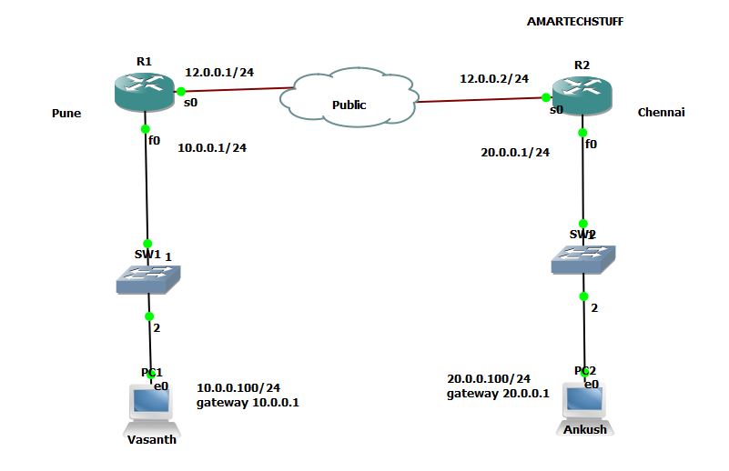
SITE - TO -SITE IPSEC VPN CONFIGURATION


INTERFACES STATUS
=========================

R1#sh int des | i up
Fa0                            up             up       LAN
Se0                            up             up       WAN
R1#sh ip int brief | i up
FastEthernet0              10.0.0.1        YES NVRAM  up                    up
Serial0                    12.0.0.1        YES NVRAM  up                    up

R2#sh int des | i up
Fa0                            up             up       LAN
Se0                            up             up       WAN
R2#sh ip int brief | i up
FastEthernet0              20.0.0.1        YES NVRAM  up                    up
Serial0                    12.0.0.2        YES NVRAM  up                    up

ABLE TO PING FROM PC1 TO PC2 & VICEVERSA
=========================================
PC1> ping 20.0.0.100
84 bytes from 20.0.0.100 icmp_seq=1 ttl=62 time=36.002 ms
84 bytes from 20.0.0.100 icmp_seq=2 ttl=62 time=58.003 ms
84 bytes from 20.0.0.100 icmp_seq=3 ttl=62 time=43.003 ms
84 bytes from 20.0.0.100 icmp_seq=4 ttl=62 time=43.003 ms
84 bytes from 20.0.0.100 icmp_seq=5 ttl=62 time=44.002 ms

PC2> ping 10.0.0.100
84 bytes from 10.0.0.100 icmp_seq=1 ttl=62 time=54.003 ms
84 bytes from 10.0.0.100 icmp_seq=2 ttl=62 time=53.003 ms
84 bytes from 10.0.0.100 icmp_seq=3 ttl=62 time=42.002 ms
84 bytes from 10.0.0.100 icmp_seq=4 ttl=62 time=38.002 ms
84 bytes from 10.0.0.100 icmp_seq=5 ttl=62 time=40.002 ms

Step 1:-  Create ACL to define Interesting Traffic.
Step 2:- Define parameters for IKE Phase1 Tunnel (ISAKMP Tunnel)
      a) Enable Crypto ISAKMP
      b) Configure HAGLE PARAMTERS
      c) Set peer & key
Step 3:- Define parameters for IKE Phase2 Tunnel (IPSec Tunnel)
Step 4 :- Create Crypto map and apply to the appropriate interface.

**** every command begins with crypto ****

STEP 1  - Create ACL to define "Interesting" Traffic
=====================================================

R1(config)#access-list 100 permit ip 10.0.0.0 0.0.0.255 20.0.0.0 0.0.0.255
R2(config)#access-list 100 permit ip 20.0.0.0 0.0.0.255 10.0.0.0 0.0.0.255

note :- we can acls with different acl numbers on both the vpn devices.

STEP 2 - Define parameters for IKE Phase 1 Tunnel (ISAKMP Tunnel)
==================================================================
a) Enable Crypto ISAKMP
==================================================================
R1#sh crypto isakmp policy
ISAKMP is turned off
R2#sh crypto isakmp policy
ISAKMP is turned off

R1(config)#crypto isakmp enable
Mar 13 02:24:38.171: %CRYPTO-6-ISAKMP_ON_OFF: ISAKMP is ON
R1#sh cry isakmp policy

Global IKE policy
Default protection suite
        encryption algorithm:   DES - Data Encryption Standard (56 bit keys).
        hash algorithm:         Secure Hash Standard
        authentication method:  Rivest-Shamir-Adleman Signature
        Diffie-Hellman group:   #1 (768 bit)
        lifetime:               86400 seconds, no volume limit


NOTE :- By default there is one IKE PHASE 1 ISAKMP Policy present.

R2(config)#crypto isakmp enable
Mar 13 02:26:44.519: %CRYPTO-6-ISAKMP_ON_OFF: ISAKMP is ON

b) Configure HAGLE PARAMTERS
==================================================================
R1(config)#crypto isakmp policy 10
R1(config-isakmp)#hash sha
R1(config-isakmp)#authentication pre-share
R1(config-isakmp)#group 5
R1(config-isakmp)#encryption aes
R1(config-isakmp)#^Z

R1#sh crypto isakmp policy

Global IKE policy
Protection suite of priority 10
        encryption algorithm:   AES - Advanced Encryption Standard (128 bit keys).
        hash algorithm:         Secure Hash Standard
        authentication method:  Pre-Shared Key
        Diffie-Hellman group:   #5 (1536 bit)
        lifetime:               86400 seconds, no volume limit
Default protection suite
        encryption algorithm:   DES - Data Encryption Standard (56 bit keys).
        hash algorithm:         Secure Hash Standard
        authentication method:  Rivest-Shamir-Adleman Signature
        Diffie-Hellman group:   #1 (768 bit)
        lifetime:               86400 seconds, no volume limit

R2(config)#crypto isakmp policy 10
R2(config-isakmp)#hash sha
R2(config-isakmp)#authentication pre-share
R2(config-isakmp)#group 5
R2(config-isakmp)#encryption aes
R2(config-isakmp)#^Z

R2#sh crypto isakmp policy

Global IKE policy
Protection suite of priority 10
        encryption algorithm:   AES - Advanced Encryption Standard (128 bit keys).
        hash algorithm:         Secure Hash Standard
        authentication method:  Pre-Shared Key
        Diffie-Hellman group:   #5 (1536 bit)
        lifetime:               86400 seconds, no volume limit
Default protection suite
        encryption algorithm:   DES - Data Encryption Standard (56 bit keys).
        hash algorithm:         Secure Hash Standard
        authentication method:  Rivest-Shamir-Adleman Signature
        Diffie-Hellman group:   #1 (768 bit)
        lifetime:               86400 seconds, no volume limit

c) Set peer & key
==================================================================
R1(config)#crypto isakmp key ?
  0  Specifies an UNENCRYPTED password will follow
  6  Specifies an ENCRYPTED password will follow
  note - both the keys will go encrypted over public network ...it is how the key will be locally

R1(config)#crypto isakmp key 0 cisco123 address 12.0.0.2
R1#sh crypto isakmp key
Keyring               Hostname/Address                   Preshared Key

default               12.0.0.2                           cisco123

R2(config)#crypto isakmp key 0 cisco123 address 12.0.0.1

R2#sh crypto isakmp key
Keyring               Hostname/Address                   Preshared Key

default               12.0.0.1                           cisco123
R2#

====================================================================================================================================
Step 3:- Define parameters for IKE Phase2 Tunnel (IPSec Tunnel)
==================================================================

R1(config)#crypto ipsec transform-set AMARTECH esp-aes 128 esp-md5-hmac
R1(cfg-crypto-trans)#^Z
R1#sh crypto ipsec transform-set
Transform set AMARTECH: { esp-aes esp-md5-hmac  }
   will negotiate = { Tunnel,  },
R2(config)#crypto ipsec transform-set AMARTECH esp-aes 128 esp-md5-hmac
R2(cfg-crypto-trans)#^Z
R2#
R2#config
Mar 13 03:07:38.415: %SYS-5-CONFIG_I: Configured from console by console
R2#sh crypto ipsec transform-set
Transform set AMARTECH: { esp-aes esp-md5-hmac  }
   will negotiate = { Tunnel,  },

====================================================================
Step 4 :- Create Crypto map and apply to the appropriate interface.
====================================================================

R1(config)#crypto map TECHMAP 10 ipsec-isakmp
% NOTE: This new crypto map will remain disabled until a peer
        and a valid access list have been configured.
R1(config-crypto-map)#set peer 12.0.0.2
R1(config-crypto-map)#match address 100
R1(config-crypto-map)#set transform-set AMARTECH
R1(config-crypto-map)#^Z


R2(config)#crypto map TECHMAP 10 IPsec-ISakmp
% NOTE: This new crypto map will remain disabled until a peer
        and a valid access list have been configured.
R2(config-crypto-map)#set peer 12.0.0.1
R2(config-crypto-map)#match address 100
R2(config-crypto-map)#set transform-set AMARTECH
R2(config-crypto-map)#^Z

R1#sh crypto map
Crypto Map "TECHMAP" 10 ipsec-isakmp
        Peer = 12.0.0.2
        Extended IP access list 100
            access-list 100 permit ip 10.0.0.0 0.0.0.255 20.0.0.0 0.0.0.255
        Security association lifetime: 4608000 kilobytes/3600 seconds
        PFS (Y/N): N
        Transform sets={
                AMARTECH,
        }
        Interfaces using crypto map TECHMAP:

R2#sh crypto ma
Crypto Map "TECHMAP" 10 ipsec-isakmp
        Peer = 12.0.0.1
        Extended IP access list 100
            access-list 100 permit ip 20.0.0.0 0.0.0.255 10.0.0.0 0.0.0.255
        Security association lifetime: 4608000 kilobytes/3600 seconds
        PFS (Y/N): N
        Transform sets={
                AMARTECH,
        }
        Interfaces using crypto map TECHMAP:

R1(config)#int s0
R1(config-if)#crypto map TECHMAP
R1(config-if)#^Z
R1#

R1#sh crypto map
Crypto Map "TECHMAP" 10 ipsec-isakmp
        Peer = 12.0.0.2
        Extended IP access list 100
            access-list 100 permit ip 10.0.0.0 0.0.0.255 20.0.0.0 0.0.0.255
        Current peer: 12.0.0.2
        Security association lifetime: 4608000 kilobytes/3600 seconds
        PFS (Y/N): N
        Transform sets={
                AMARTECH,
        }
        Interfaces using crypto map TECHMAP:
                Serial0

R2(config)#int s0
R2(config-if)#cry
R2(config-if)#crypto map TECHMAP
R2(config-if)#^Z
R2#sh crypto map
Crypto Map "TECHMAP" 10 ipsec-isakmp
        Peer = 12.0.0.1
        Extended IP access list 100
            access-list 100 permit ip 20.0.0.0 0.0.0.255 10.0.0.0 0.0.0.255
        Current peer: 12.0.0.1
        Security association lifetime: 4608000 kilobytes/3600 seconds
        PFS (Y/N): N
        Transform sets={
                AMARTECH,
        }
        Interfaces using crypto map TECHMAP:
                Serial0

========================================================================

R1#sh cry isakmp sa
dst             src             state          conn-id slot status

R1#sh cry ipsec
R1#sh cry ipsec sa

interface: Serial0
    Crypto map tag: TECHMAP, local addr 12.0.0.1

   protected vrf: (none)
   local  ident (addr/mask/prot/port): (10.0.0.0/255.255.255.0/0/0)
   remote ident (addr/mask/prot/port): (20.0.0.0/255.255.255.0/0/0)
   current_peer 12.0.0.2 port 500
     PERMIT, flags={origin_is_acl,}
    #pkts encaps: 0, #pkts encrypt: 0, #pkts digest: 0
    #pkts decaps: 0, #pkts decrypt: 0, #pkts verify: 0
    #pkts compressed: 0, #pkts decompressed: 0
    #pkts not compressed: 0, #pkts compr. failed: 0
    #pkts not decompressed: 0, #pkts decompress failed: 0
    #send errors 0, #recv errors 0

     local crypto endpt.: 12.0.0.1, remote crypto endpt.: 12.0.0.2
     path mtu 1500, ip mtu 1500, ip mtu idb Serial0
     current outbound spi: 0x0(0)

     inbound esp sas:

     inbound ah sas:

     inbound pcp sas:

     outbound esp sas:

     outbound ah sas:

     outbound pcp sas:

======================================================================================================

R1#sh cry isakmp sa
dst             src             state          conn-id slot status
12.0.0.2        12.0.0.1        QM_IDLE              1    0 ACTIVE

R2#sh cry isakmp sa
dst             src             state          conn-id slot status
12.0.0.2        12.0.0.1        QM_IDLE              1    0 ACTIVE


R1#sh cry ipsec sa

interface: Serial0
    Crypto map tag: TECHMAP, local addr 12.0.0.1

   protected vrf: (none)
   local  ident (addr/mask/prot/port): (10.0.0.0/255.255.255.0/0/0)
   remote ident (addr/mask/prot/port): (20.0.0.0/255.255.255.0/0/0)
   current_peer 12.0.0.2 port 500
     PERMIT, flags={origin_is_acl,}
    #pkts encaps: 21, #pkts encrypt: 21, #pkts digest: 21
    #pkts decaps: 21, #pkts decrypt: 21, #pkts verify: 21
    #pkts compressed: 0, #pkts decompressed: 0
    #pkts not compressed: 0, #pkts compr. failed: 0
    #pkts not decompressed: 0, #pkts decompress failed: 0
    #send errors 1, #recv errors 0

     local crypto endpt.: 12.0.0.1, remote crypto endpt.: 12.0.0.2
     path mtu 1500, ip mtu 1500, ip mtu idb Serial0
     current outbound spi: 0xA9BA9F1(177973745)

     inbound esp sas:
      spi: 0x3637026C(909574764)
        transform: esp-aes esp-md5-hmac ,
        in use settings ={Tunnel, }
        conn id: 2002, flow_id: SW:2, crypto map: TECHMAP
        sa timing: remaining key lifetime (k/sec): (4525445/3524)
        IV size: 16 bytes
        replay detection support: Y
        Status: ACTIVE

     inbound ah sas:

     inbound pcp sas:

     outbound esp sas:
      spi: 0xA9BA9F1(177973745)
        transform: esp-aes esp-md5-hmac ,
        in use settings ={Tunnel, }
        conn id: 2001, flow_id: SW:1, crypto map: TECHMAP
        sa timing: remaining key lifetime (k/sec): (4525445/3522)
        IV size: 16 bytes
        replay detection support: Y
        Status: ACTIVE

     outbound ah sas:

     outbound pcp sas:

R2#sh crypto ipsec sa

interface: Serial0
    Crypto map tag: TECHMAP, local addr 12.0.0.2

   protected vrf: (none)
   local  ident (addr/mask/prot/port): (20.0.0.0/255.255.255.0/0/0)
   remote ident (addr/mask/prot/port): (10.0.0.0/255.255.255.0/0/0)
   current_peer 12.0.0.1 port 500
     PERMIT, flags={origin_is_acl,}
    #pkts encaps: 67, #pkts encrypt: 67, #pkts digest: 67
    #pkts decaps: 67, #pkts decrypt: 67, #pkts verify: 67
    #pkts compressed: 0, #pkts decompressed: 0
    #pkts not compressed: 0, #pkts compr. failed: 0
    #pkts not decompressed: 0, #pkts decompress failed: 0
    #send errors 0, #recv errors 0

     local crypto endpt.: 12.0.0.2, remote crypto endpt.: 12.0.0.1
     path mtu 1500, ip mtu 1500, ip mtu idb Serial0
     current outbound spi: 0x3637026C(909574764)

     inbound esp sas:
      spi: 0xA9BA9F1(177973745)
        transform: esp-aes esp-md5-hmac ,
        in use settings ={Tunnel, }
        conn id: 2002, flow_id: SW:2, crypto map: TECHMAP
        sa timing: remaining key lifetime (k/sec): (4467647/3445)
        IV size: 16 bytes
        replay detection support: Y
        Status: ACTIVE

     inbound ah sas:

     inbound pcp sas:

     outbound esp sas:
      spi: 0x3637026C(909574764)
        transform: esp-aes esp-md5-hmac ,
        in use settings ={Tunnel, }
        conn id: 2001, flow_id: SW:1, crypto map: TECHMAP
        sa timing: remaining key lifetime (k/sec): (4467647/3443)
        IV size: 16 bytes
        replay detection support: Y
        Status: ACTIVE

     outbound ah sas:

     outbound pcp sas:


Thanks for Reading !!!!!!